Lab 2
IMU
In this lab, I familiarized myself with the IMU.
In this lab, I familiarized myself with the IMU.
To prepare for this lab, I read up on the datasheet of the IMU sensor and skimmed the instructions.
The first task was to run the basics code in the given examples. The AD0_VAL default is 1. In the code if we set the value to 0, it uses a different i2c address. Thus this ADO_VAL represents the last bit in the i2c address. As I played around with the sensor, I noticed that the gyroscope would read a value meainly when the sensor was rotating a lot while the accelerometer would read values when the sensor was physically moving up/down and left/right. After flipping the sensor a few times, I noticed at certain positions the sensor values would go negative. After this I coded a visual indicator that the board was running by having the built in LED blink 3 times slowly on startup. Below is a video of this blinking.
The second task was to test with the accelerometer sensor. I used the equations from class to convert this data into pitch and roll. In addition I used atan2() to ensure that the data was in the proper quadrants. Below is a video of when the accelerometer output is {-90, 0, 90} degrees pitch and roll and code of the equations I used. The accelerometer was pretty accurate in that the degrees is only off by a one or two degrees. As such I felt that we didn’t need to do two-point calibration.

The next task was to analyze the noise in the frequency spectrum. I took the Fourier transform of the pitch and roll data and at first I noticed when the IMU was stationary, I only got noise at 0Hz. After consulting others, I realized I needed to add some movement to actually get the frequency of the signal so I added some sinusoidal movements and random vibrations to get the signal. I printed out the pitch and roll data and took the FFT of this.
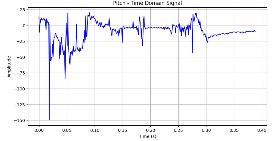
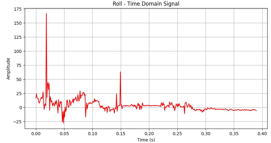
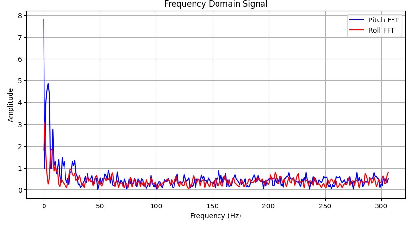
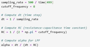
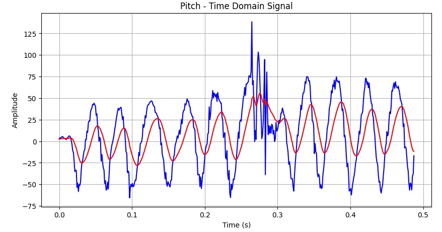
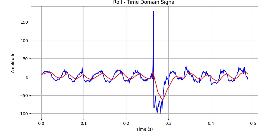
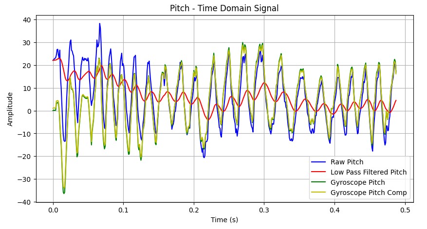
Next I indexed through the FFT graph to decide on my cutoff filter. I decided on a cutoff filter at 8Hz because with the movement of the sensor, I noticed most of the noise died down later at around 8Hz. Based off formulas from class, I calculated my alpha value to be around 0.046. I got my sampling rate from dividing the amount of messages I got (500) by the time stamp of the last data point. From this I calculated by time step and RC constant to get alpha. Below is the code I used to calculate alpha. I once again tested my low pass filter by moving the sensor sinusoidally to get a clear wave. Below are the images of the pitch and roll compared with its low pass values and how I calculated the LPF values. As you can see, the noise and random spikes in the data are smoothed out. In fact it seemed like the filtering was too much which might suggest needing a larger alpha value but I did not decide to optimize more.

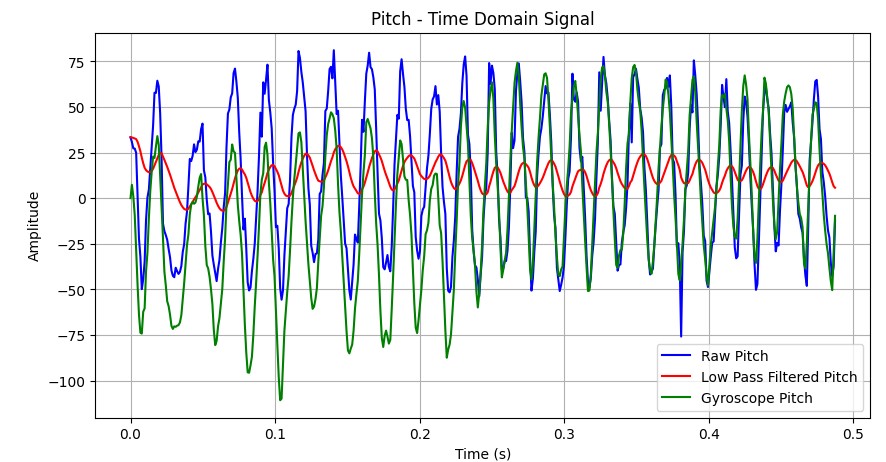
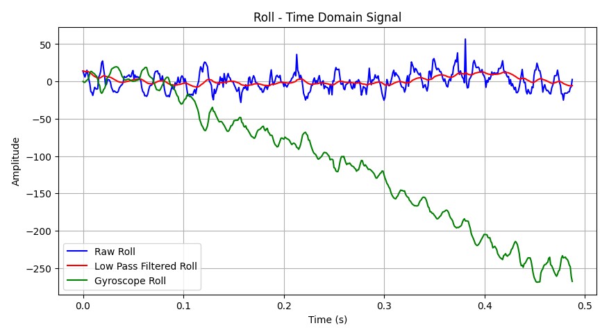
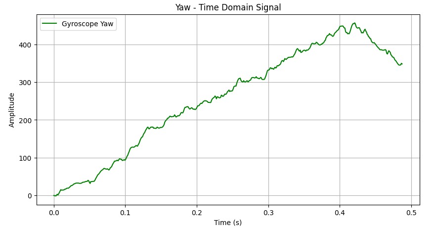
After playing around with the accelerometer, I went on to the gyroscope and used equations from class to calculate the pitch, roll, and yaw. Because the gyroscope measures angular velocity, I noticed that I would have to calculate dt that I could integrate the gyroscope velocity and add to the previous roll, pitch, and yaw. The gyroscope values for roll and pitch seemed to drift more than the accelerometer but they were less noisy so in the beginning the values were pretty accurate but after that, they didn't match anymore. I found that my low pass filtered pitch and roll values were the least noisy but that was probably due to my chosen alpha value that did filter a lot of the noise. I also noticed that the roll and yaw would drift much more than the pitch values which was probably due to how I was moving the sensor sinusoidally. Below is the comparisons between the accelerometer and the gyroscope. I also noticed with a larger sampling rate, the accuracy was much better. The accelerometer values were much better but the gyroscope values still drifted over time.
After calculating the pitch, roll, and yaw of the gyroscope, I wanted to fix this drift so I implemented a complementary filter to compute an estimate of the pitch and roll that was both accurate and stable. I decided to use a larger alpha value this time and chose it to be 0.8 because the gyroscope was generally more accurate but just drifted, so I used a larger alpha value to leverage this. Below is the comparison of the pitch and roll values of the gyroscope with the filter. I tested my implementation with first staying still then moving the sensor sinusoidally again to test its robustness.

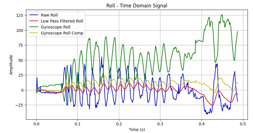
As seen the pitches with the complementary filter do not drift as much while the roll values do drift a little bit but compared to the raw values, it does not drift as much as it uses the low pass filter value to situate itself.
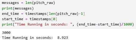
Finally to speed it up, I commented out all the delays and serial print statements in my arduino code. I noticed that the code indeed did run faster and the rate of messages sent were much faster as well. Previously the data rate with all the print statements was that 500 messages took around 10 seconds to create. Once I deleted all the prints and delays I was able to send around 2000 messages within 5 seconds.
I calculated this new message rate by sending out timestamps in addition to my data and I subtracted the ending message and starting message time stamp to get the total time it took to get that data. I made sure that the board could collect up to 5 seconds of data using this method. The calculated message rate was 336 messages/ second.
I decided to use small float arrays for each of the data points but decided to send everything in one big array from the results of Lab 1. I decided to have small arrays for the data points for ease of use in coding so I wouldn't have to spend time decoding the arrays. Each arrays can take up 1/3 of the data available on the Artemis since the data is stored by accelerometer, gyroscope, and TOF separately. With 384000 bytes on the Artemis and each float per array taking up 4 bytes of data, this is about 32000 data points. With my sampling rate of around 3 milliseconds, this is the equivalent of 96 seconds of data. Below is a screenshot of how I ensured it ran for 5 seconds.
While manuevering the car with the remote, I noticed it was pretty hard to control and the car moved very fast. I was able to make the car do some cool tricks and fall on its side to continue spinning. I also noticed that even when making the car go straight using the remote, the car still would not go straight and it would start to drift to the side.