Lab 3
IMU
In this lab, I familiarized myself with the TOF.
In this lab, I familiarized myself with the TOF.
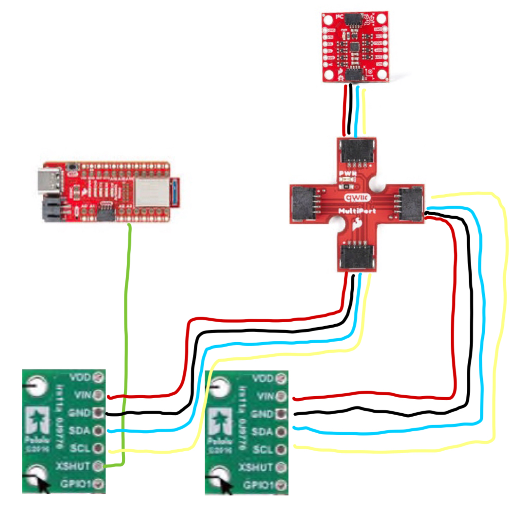
To prepare for this lab, I read up on the datasheet of the TOF sensor. From the datasheet I figured out that the device addrress was 0x52. However to prepare for the 2 sensors, I needed to solder the XSHUT pin to the Artemis Nano board. This was done to temporarily shut off one of the sensors so that the I2C address could be changed to the other and we could have both communicating. This was better than having to solder two XSHUT pins. For the placement of these sensors on the car, I plan to have the TOF sensors on opposite ends front and back of the car. Thus I used the longer QWIIC connectors to facilitate this. This placement would be best because it would allow me to detect obstacles in the front and back of the car when the car is moving forwards and backward. This might cause the robot to miss obstacles on the sides but I anticipate that the car will not be rotating that much. As shown below, this is what I expect my wiring to be.
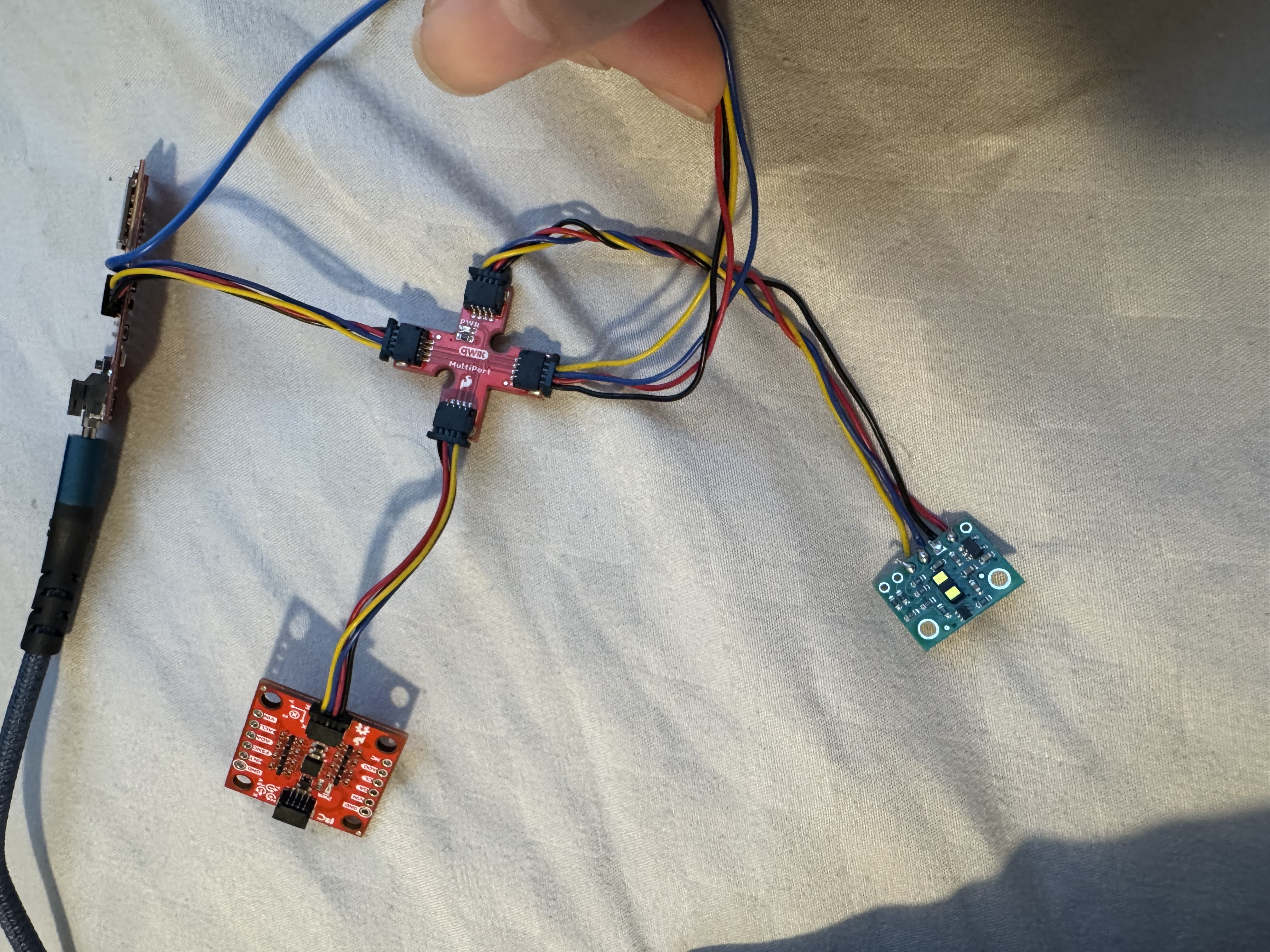
The first task was to hook everything up and solder the batteries and the TOF sensor. First I soldered the battery wires to the JST jumper wires and used a multimeter to test if I soldered them correctly. I also used heat shrink to protect the wires from possibly touching. I powered the Artemis with this battery instead of the USB-C and tested its BLE capabilities. Below is an image of the setup where the TOF is connected to the Artemis.
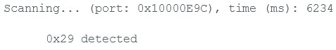
The second task was to scan the I2C channel to find the sensor. I used the example files to see this and get familiarized with i2c commands. I found that the code looked for 2 i2c devices but it did manage to find my device. The address was not what I expected since I thought according to the data sheet the address was 0x52 it was 0x29. This was because the address seemed to be bit shifted to the right since the most significant bit was used to determine whether the data was being written or read.
The next task was to decide on a good sensor mode. After looking through the datasheet, I found that there were three modes for the final robot: .setDistanceModeShort(), .setDistanceModeMedium(), and .setDistanceModeLong(). I found that the distance mode for the short rnage had a maximum detectable distance of 1.3m and had better ambient immunity where it was less susceptible to noise. The other ranges were much larger but were more susceptible to this ambient noise. Thus since the robot probably didn't need to see farther than 1 meter, I chose the short distance mode. As seen below is a video of me testing with the short distance mode and the data I was getting.
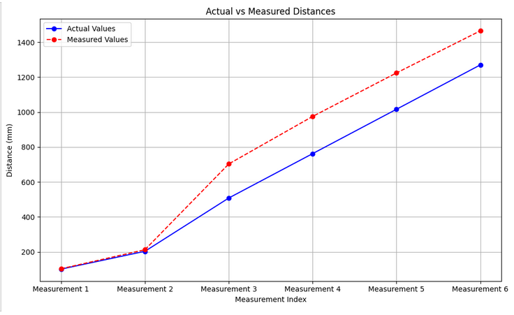
Next I wanted to determine the sensor's sensor range, accuracy, repeatability, and ranging time. To test my TOF sensor in short mode, I taped one of the sensors flat on my laptop and used a tape measure to set up different distances from the wall. I decided to take take 10 different sensor measurements at 6 different distances. To check the accuracy of the sensors, I plotted the average values I calcuated and compared them with the actual distances. This experiment however had a lot of possible room for human error. I believe I might have been calculating the distance correctly when it was much closer to a wall but as it got larger, the error increased. This might have been a human error since the distance did increase the same rate. My laptop lid was very flimsy.
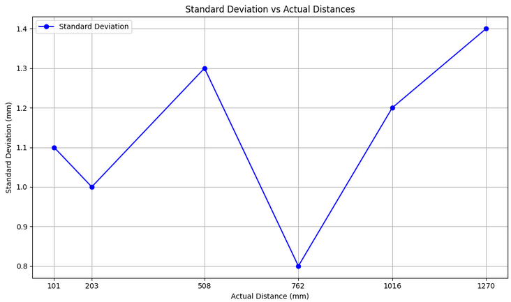
After this I wanted to test repeatability. I had already taken 10 measurements for 6 distances so I just graphed these out and figured out the standard deviations as well as how it compared against the actual distance.
To measure the ranging time, I took the starting and ending times of the data collection loop. By getting rid of superfluous code in between my start and stop ranging functions, I managed to get to 3ms ranging time. I noticed if I added more logic in between the ranging time would go up to 50 ms.
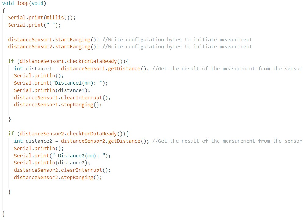
After getting the necessary sensor's data, I hooked up 2 TOF sensors together and I had to modify the code to collect sensors from both. To do this I had to toggle between the values of the XSHUT pin to change the address of the sensors. I also optimized my code so that it would take in data much faster. To do this I used distanceSensor.checkForDataReady() to check when new data was available rather than having my code hand while it waits for the sensor to finish measuring. I printed out the time stamps to determine how fast my loop was executing. It is around 6-7 ms every time reading and around 46-50 ms for every time it detects a change in the two distance sensors. If one distance sensor changes the reading the time is around 20-25 ms. Some Possible limiting factors are that the data is not available everytime through the loop (due to the checkForDataReady() if statement) or there needs to be some delay in between for the data to be read and then written.
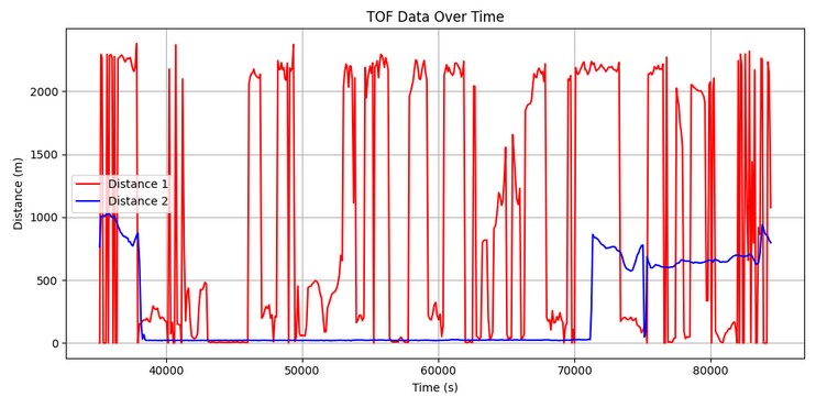
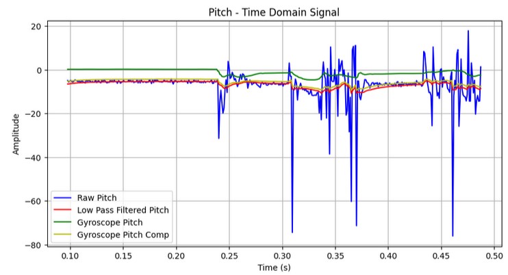
Eventually I combined my code from lab 1 to plot the TOF data over time. In addition to this I also plotted my IMU data to plot over time. I structured my code so that it would get these sensor readings all in parallel.
Some common sensors are are infrared triangulation sensors and passive infrared (PIR) sensors. Infrared triangulation sensors emit IR light onto an object and measure the reflection angle using a position-sensitive detector to determine the distance. They offer good accuracy for short ranges but can be affected by ambient noise. On the other hand, PIR sensors detect infrared radiation emitted by objects rather than sending out IR signals. They are more used for motion detection rather than precise distance measurement since they use heat patterns. While PIR sensors are energy-efficient and work well in darkness, they cannot determine exact distances or detect stationary objects. Infrared triangulation is better for short-range precision, but PIR sensors are better in motion detection applications like security systems.
Finally to test this, I used the example Read distance code and introduced different ambinent noise through different colors and textures around the sensor. I compared my readings with less ambient noise and found out that the sensor was a little sensitive to the noise and its readings were a little different. Sometimes I would get outliers in the distance readings due to this.