Lab 4
Motors and Open Loop Control
In this lab,I combined all the sensors from previous labs and worked with the motor driver to set up the car and make it move.
In this lab,I combined all the sensors from previous labs and worked with the motor driver to set up the car and make it move.
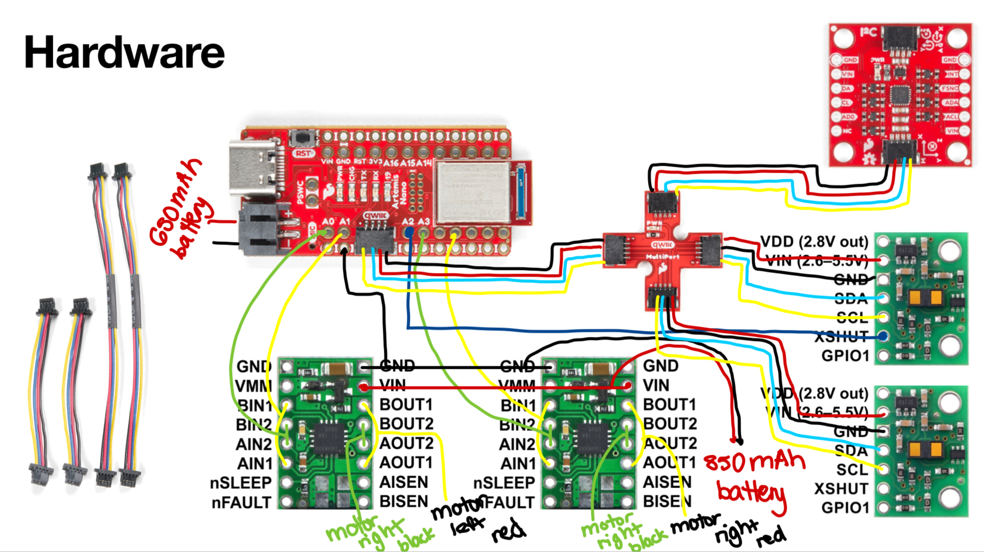
To prepare for this lab, I checked out the datasheet and documentation for the dual motor driver to get a sense of the pins needed. To deliever enought current for our robot to be fast I used the lectures from class to get a sense of how to parallel couple the two inputs and outputs on each motor driver. After this I picked pins A0 and A1 on the Artemis to control the first motor driver and I picked pins A3 and A5 to control the other motor driver. I picked these pins because of how the artemis was going to be placed in the car, I wanted to make sure the pins I were using would output PWM signals as well as was on the same side of the Artemis board.
We power the Artemis and the motor drivers from separate batteries because if we powered it all from the same battery it would be possible that there is not enough current to power the Artemis since the current demand is so high. This can cause voltage drops and instability in the Artemis.
When considering the routing for all the components of the board, I knew I wanted smaller length wires to connect the motor driver to the artemis and the motors because they were all pretty close together in the chassis of the car. I kept the TOF sensors to be longer since they would be on the front and side of the car and I chose a shorter wire for the IMU since it would be close to the artemis. I decided to continue to use the QWIIC breakout board and the connector cables for the TOF and IMU sensors because the cables I picked from previous labs were long enough. I decided to color code my motor driver pins so I set up all the inner parallel pins to be green and the outer parallel pins to be yellow for ease of use and understanding. I decided to use stranded wire rather than solid core to account for the car undergoing high accelerations.
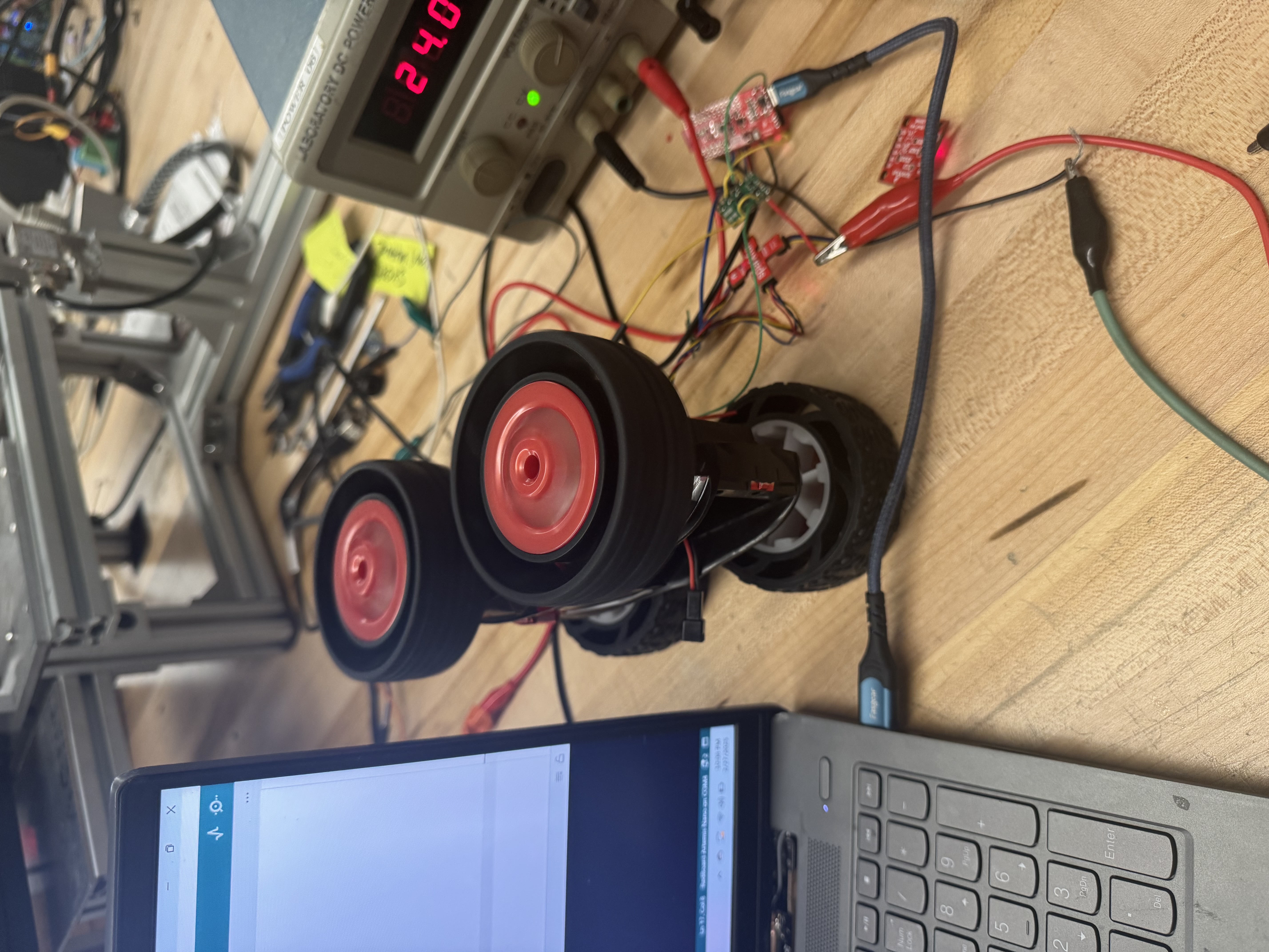
The first task was to hook everything up and solder the motor drivers. I first started with soldering the first motor driver and connected it with the Artemis and a power supply that was set to 3.7 Volts. Some reasonable settings for the power supply was a current that was a little higher than 0 A so around 0.2 A and I noticed that that 2.7V was enought to power the motor driver from the datasheet but I increased it to 3.7V so it would be consistent with the battery.
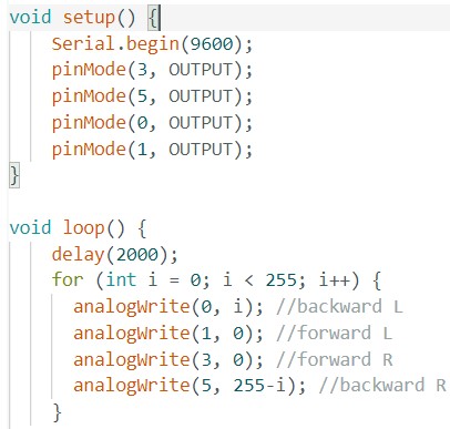
I then wrote some simple code to generate the PWM signals using AnalogWrite as shown below. I took inspiration from Nila Narayan to cycle through the PWM signal values.
I probed the out signals using the PWM to see my signals and noticed it had a lot of coupling due to how I wired it. I had initially used a lot of loops in my motor driver to parallel couple the inputs and outputs but after seeing the messy outputs I decided to resolder my motor driver to remove the loops and decrease the EMI and coupling of the wires. I was able to get cleaner PWM signals that were a square wave.
After ensuring that my PWM signals were clean, I took my car apart and removed the internal PCB. I connected the motor driver outputs to the motor wires. I still kept my motor driver powered on an external power supply and I ensured that they all shared the same ground. I then wrote code to test the wheels spinning to ensure that it could spin forwards and backwards. After getting one wheel to turn forward and back, I started to solder the second motor driver and connecting it with the rest of the components. After getting the wheels working on the power supply I switched to the battery and tested on that. Below are videos of the individual sides of the wheels spinning forwards and backwards as well as both wheels spinning with the battery driving the motor drivers.
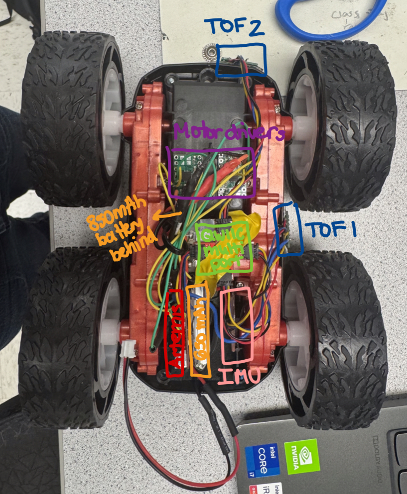
After ensuring that the car wheels were moving forwards and backwards, I installed everythig inside the car chassis. I used double sided tape and zip ties to ensure everything was secure and inside the car. Below is an image of my setup.
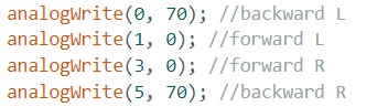
After getting both wheeels turning, I started figuring out the lower limit PWM for when the robot starts to move forward. I decided to do this experimentally by manually changing the PWM values in groups of 10 rather than using a for loop to slowly increase the value because I wanted to see the robot move for a while. I managed to find that the minimum value for the robot to move forward was 50 and the minimum value to turn was 70.
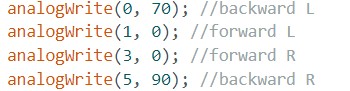
While running the wheels at the same PWM value, I noticed that the left wheel would run much faster than the right wheel. I implemented a calibration factor by just changing the values until I saw the wheels turn at the same rate. I ended up up with the left wheel at 70 and the right wheel at 90 to get them to turn at the same rate. This means the calibration factor was 1.3. Below is a screenshot of the code and video of the car moving in a straight line.
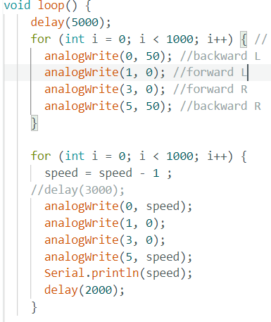
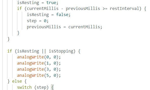
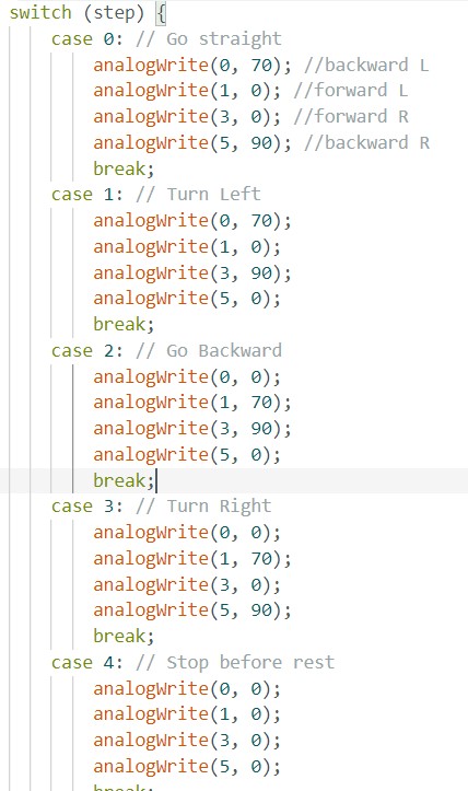
I then coded up an open loop routine for the car to go straight then turn and move and turn again. Below is a demo video of the car moving around the lab and the code. I used state variables and flags to control which action the car was going to do. I added some delays as well that were listed at the top of the code.
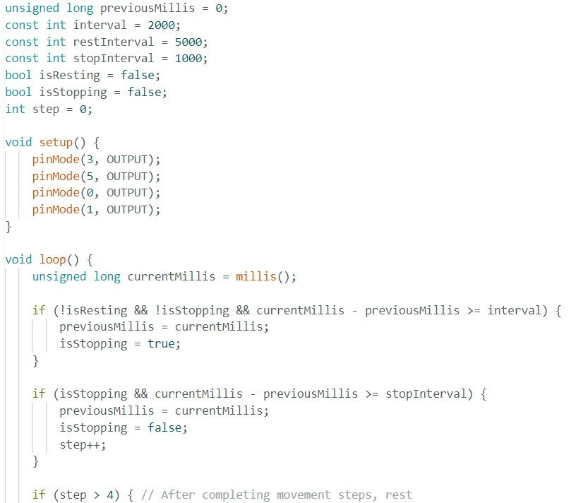
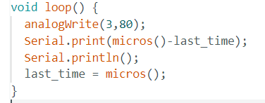
The analog Write function of the Artemis operates with a time stamp of 3ms which is a frequency of around 333Hz. This is adequately fast for these motors but we could manually configure the timers to generate a faster PWM signal. Some benefits would be it could ensure better motor control over the movement of the robot. Below is the code I used.
I used a for loop which decreasing PWM values to figure out at what value the robot kept moving once it was in motion. I wrote some code to have the car overcome its static friction first at value 50 then slowly decreased that value until I saw the wheels stop moving. I noticed that the left wheel's lowest PWM value was 26 when it started to run very slowly and the right wheel's lowest PWM value was 39. Below is the video and code of the setup.