Lab 6
Orientation PID
In this lab, I used the IMU and the TOF sensor to implement PID orientation control.
In this lab, I used the IMU and the TOF sensor to implement PID orientation control.
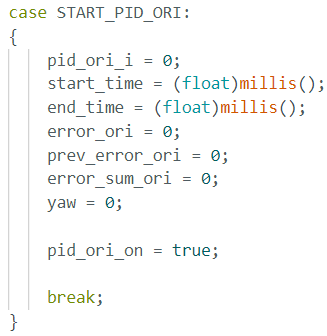
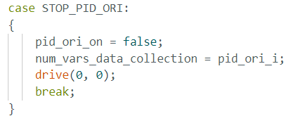
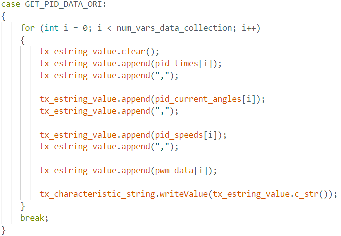
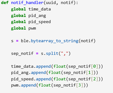
To prepare for this lab, I mainly setup the IMU data transfer the same way I did for Lab 5. I just added more boolean flags that checked whether angular PID should be on of off. I edited my notification handler to be able to handle the IMU data and the PID ANG data. I added some more commands as well: START_PID_ORI, STOP_PID_ORI. I added a GET_PID_DATA_ORI to send the new data over to debug. The implementation of these commands were similar to my implementation in Lab 5 using flags. I used the equation from class to compute the value for th ePID controller but then used trial and error. The proportional would represent the current error while the integral would count the accumulation of past errors. The derivative would predict future error.
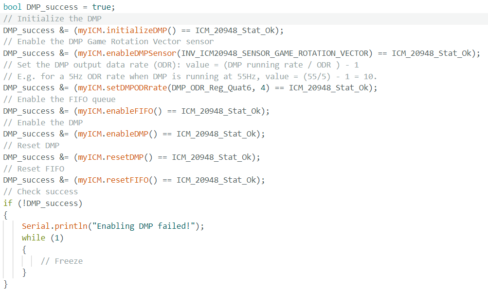
Similar to Lab 5, I used a PI Control where the pwm output was based on error and the gain value and the accumulated error. I noticed using this way that the car would often just spin around in circles a lot or it would just not move and go forwards sometimes. After talking to others in the class, I decided I actually had to first implement the DMP to allow the IMU to perform real time calibration and drift correction. I had to uncomment a line of code in the IMU library to enable the DMP. I also used the example DMP code to set it up.
I decided to use some more example code from the DMP where the code read quaternion data and it extracts the orientation data and converts it to a usable value and calculates the yaw from this. The yaw is compared to a target angle to compute an orientation error, where previously in lab 5 the error was foot distance from a wall. I then used a similar code from my P control in lab 5 for the orientation code. This time I added a timeout feature though.
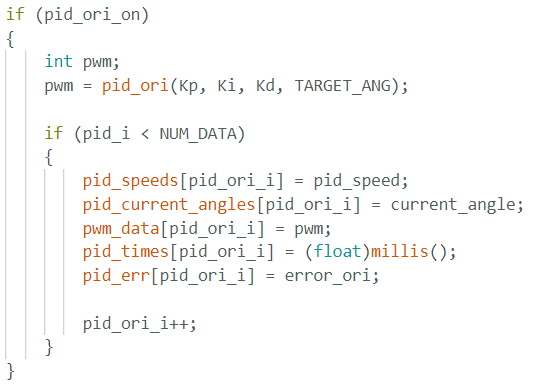
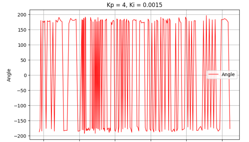
First I tried to use the same PID values where P = 0.08 and I = 0. This caused the car to not move or sometimes just go straight. This would give me no values to debug which made it seem like the data was never ready. I then started to use other Kp values. I picked a much larger Kp value of 5.0 where this worked best. I tweaked the Ki value a little bit and gave it a value of 0.0001. This yielded ok results. The car would move a lot before settling. The car would also oscillate a lot once it got into its good orientation.
Although the PI worked well somewhat, there was a lot of downtime when the TOF sensor data just wasn't ready and needed around 40 ms for a new value. Also the calculated yaw error was at most 360 degrees. I added print statements for each new IMU data to see its sampling period. The sampling frequency was around 100Hz for the measurements, This time the PID loop also ran at aroung the same speed as the gyroscope. When testing I found that the lower limit PWM where the robot would turn was actually around 75.
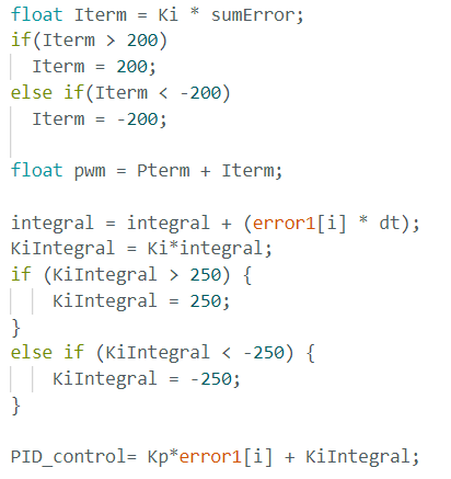
When there was no windup protection, the car would slam into the wall if it went very fast and it would also sometimes just spin really fast based on different floors. Thus wind up protection was implemented. If the value of Ki multipled by the time integrated error was greater than 250 or less than -250 the Ki Integral would be set to a constant 250 and does not change. The implementation is below. I noticed with a higher Ki values the worse the robot performed.
I referenced Nila Narayan and Mikayla Lahr for implementation.