Lab 7
Kalman Filtering
In this lab, I combined Kalman Filtering and PID control onto the robot.
In this lab, I combined Kalman Filtering and PID control onto the robot.
To build the state space model for my system, I first estimated the drag and momentum terms for my A and B matricies. I used a step response to do this and drove the car towards a wall at a constant input motor speed at a PWM value of 100 while logging the motor input vlaues and the TOF sensor output. I chose 100 because I noticed 200 to be my maximum PWM value back from lab 5 where it would still go straight. To ensure my step time was long enough to reach steady state, I tested with different intervals and found that it reached its steady state in around 1.5 seconds.
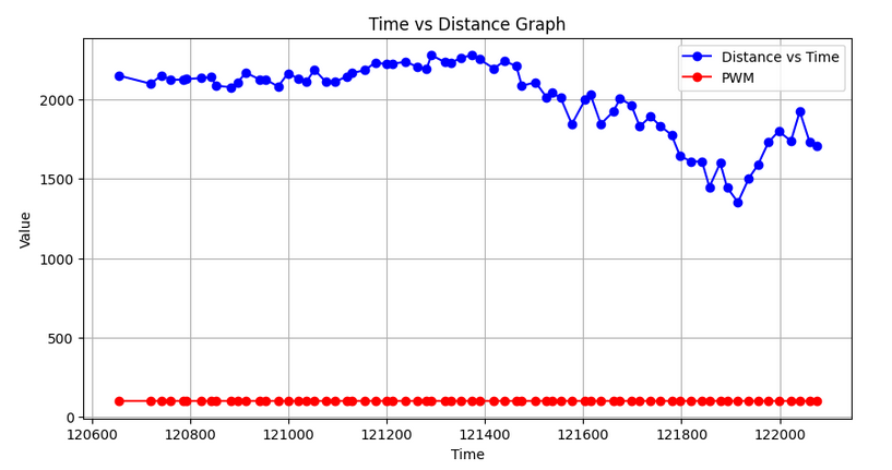
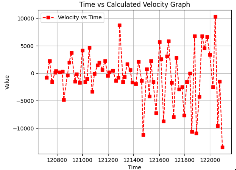
I measured the steady state speed to be around -5000 mm/sec. My TOF sensor data was pretty noisy so I eyeballed a general trend of my steady state speed after multiple runs and found that it would be around -5000 mm/sec (-4181 mm/sec). The 90% rise time was 1.34 seconds. The speed at 90% rise time was 4181* 0.9 = 3762 mm/sec. From these values I calculated the drag to be 0.000239 and the momentum to be 0.00013914795.
When I was sending this data back to my laptop, I saved the data in a csv file in python.
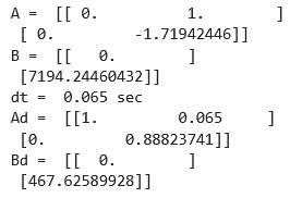
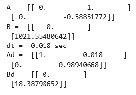
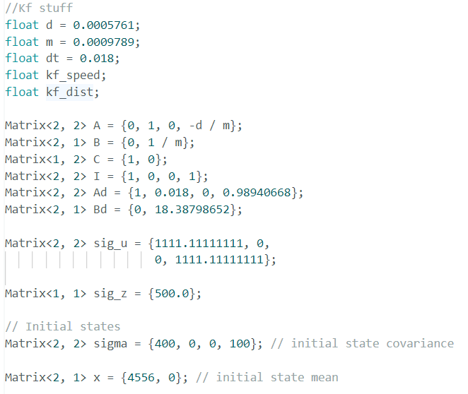
Using the calculated values for d and m, I computed the A and B matrix. From the state space equation the A and B matrices were this respectively.


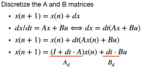
I discretized the A and B matrices using the slide from lecture 13. The sampling time was 0.065 seconds. Below are my Ad and Bd.
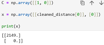
After this I identified my C matrix to be C = [1,0]. After this I initialized the state vectors where x = np.array([[cleaned_distance[0]], [0]]).
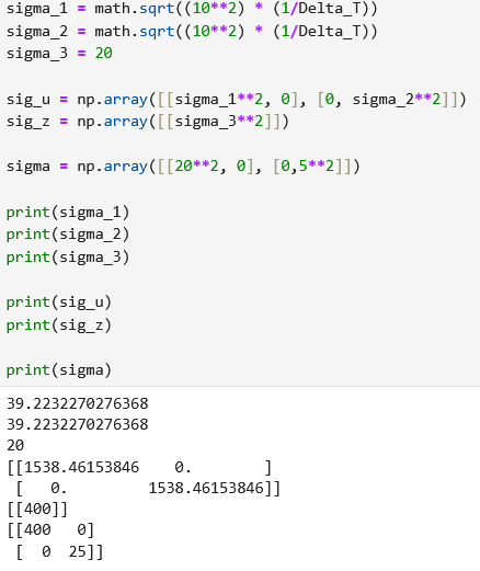
For my Kalman filter to work well I also specified my process noise and sensor noise convariance matrices. Sigma_3 was set to 20 because the TOF sensor has a ranging error of +/- 20 mm. Sigma_1 and sigma_2 was initialized using the calcualtions from Lecture 13. Sigma_1: 39.223 mm Sigma_2: 39.223 mm Sigma_3: 20mm In python the initialized sigma_1 value was 20 and 5 for sigma_2 as the robot was not moving in the beginning. With each dataset, I had to change the sigma values. Values are shown below and how they are calculated.
To check my chosen parameters from above, I implemented my Kalman Filter in Jupyter using the code provided in lab. Halfway through this lab, my TOF sensors suddenly stopped working so I had to switch to another car (Thank you Rachel). Thus I had to redo my PID terms and my KF variables to match this car. I used my code by Rachel's car to test my stuff and that was when my whole world changed. I realized throughout lab 5 to 7 I was getting weird TOF data where it was either super noisy or I wouldn't get data at all leading me to have to redo multiples tries on my code. The moment I tested my code on Rachel's car, it was like a switch happened and my code suddenly started working really well again and I was getting lots of data rather than the sporadic bursts of around 50 pieces of data in 5 seconds. Hopefully be next lab I will have figured out hardware wise whatever happened to my car and TOF sensors but now I had much more data to work with. Below are my new values with Rachel's car.
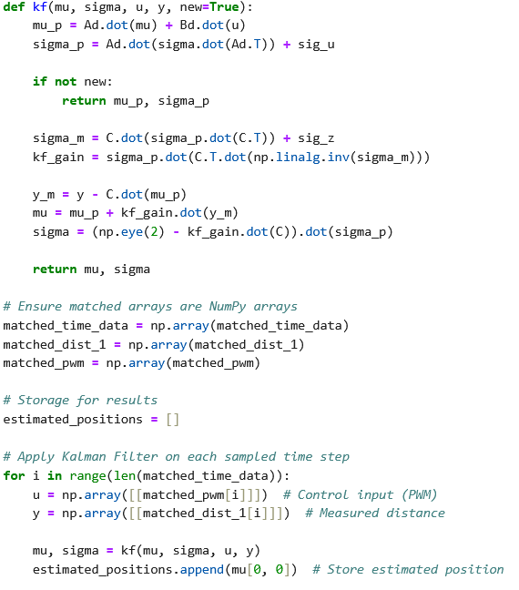
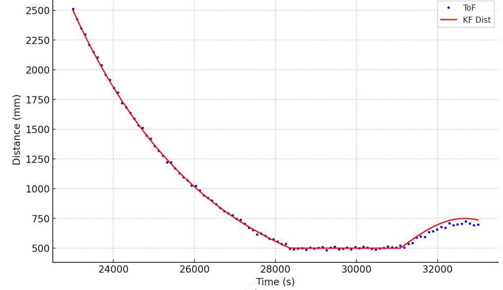
I had to import my timing, TOF, and PWM data from a straight run towards the wall. I had to format my data so that the array would have equal length by interpolating the data. I looped through my data while calling the Kalman filter. I scaled my input from 1 to the my actual step size. Below is a graph to show my best parameters to estimate the system state. I experimented with different d and m values to see how that would change my covariance matrix. Although my original values did fit ok, I found that increasing the sigma_3 values by a tiny bit gave me a worse fit. Below is with sigma_3 = 20 and the later is with sigma_3 = 25.

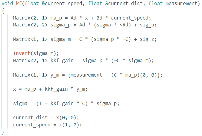
To implement the KF filter on the robot, I had to install the Basic Linear Algebra library on the arduino. I created GET_KF_DATA to debug. I also wrote a kalman filter function in Arduino IDE.
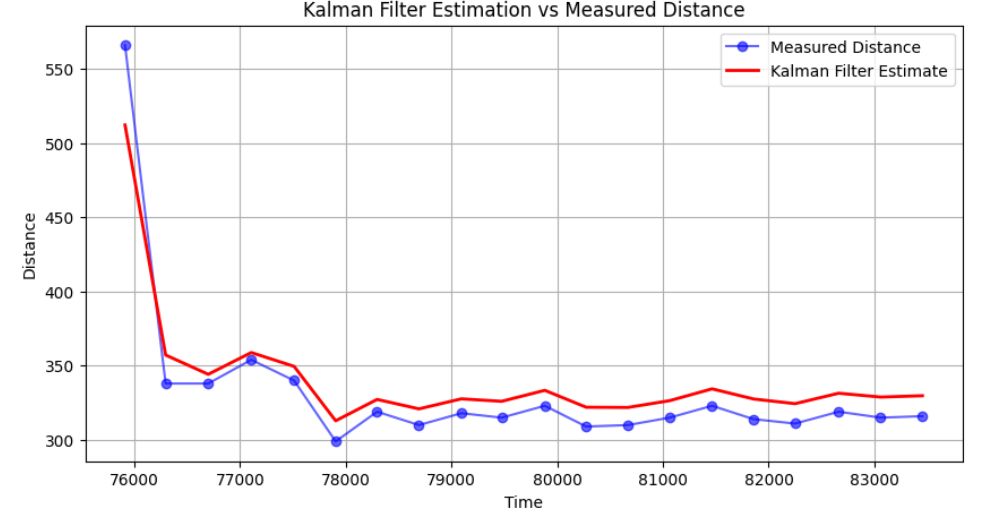
I had to also use the TOF readings for the PID loop. During this time, I had to tune my PID terms as well to get the car to work well. My PID terms were 1.4 and 0.0004 for Rachel's car. Below is graphs of the time vs distance vs the TOF distance and the Kalman Filter. Below is also the time vs the motor input. My kd = 0.015. I noticed the behaviour of the car was much better. However due to lack to time, I could not tune the PID values even more to get rid of the oscillations. In the graph below I cut off before it was oscillating a lot.
I referenced Stephan Wagner and Mikayla Lahr for implementation. I asked Lulu for some help with the Kf arduino implementation.