Lab 9
Mapping
In this lab, I mapped out a static room using the robot's TOF sensors.
In this lab, I mapped out a static room using the robot's TOF sensors.
For this lab I needed to understand the transformation matrices and set up my robot will all the working sensors. I read through the lecture on transformation matrices before starting the lab.
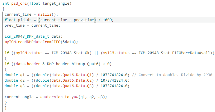
For this lab, I decided to pick option 2 orientation control to do my readings. For my PID controller I had the robot perform on axis turns in 24 degree increments. In total I had the car do around 15-16 measurements to get up to 360 degrees of mapping. I had two sensors where one was placed on the front of the car and the other sensor was placed on the left side of the car between the two wheels. At some point in the lab, the second sensor on the left side of the car started acting wonky and giving weird binary values. I also noticed the data on the left side sensor would be really noisy from the wheels so I just decided to use the first sensor on my car but made sure to do more turns to get more data. To do the mapping, I made a new case called START_MAP that would use my function pid_ori to edit the pwm values of the car while making sure the car would actually turn to the correct degrees. In this case command, I had it send over data via bluetooth as well when the mapping was done. I had it send over yaw data, TOF sensor distance data, as well as the target angles of the car and compared it to the actual yaw angles to see how well my PID loop control worked. Below is my code for START MAP.
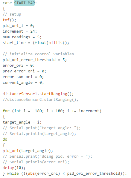
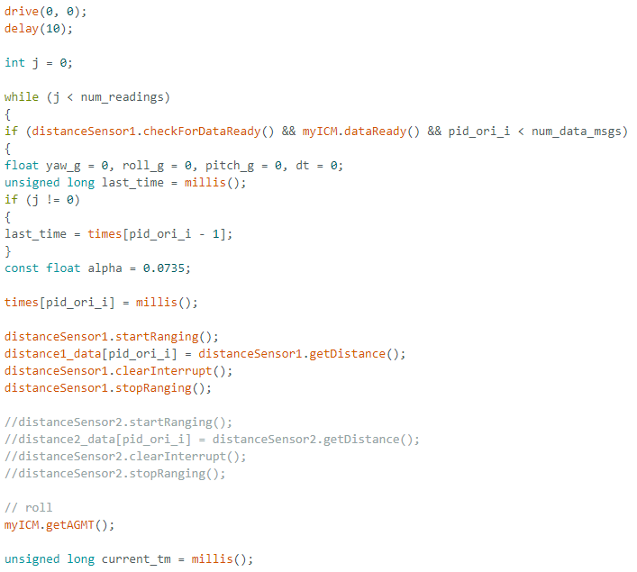
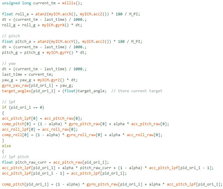
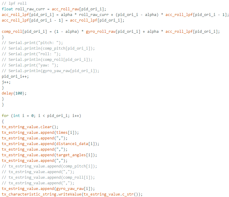
In start map I set up the increment and I chose the number of readings to be 5 so that I could average them out later to ensure that my data was sound. I also set up my increment to be 24 degrees so that I could get the necessary amount of readings to get a good mapping. In this case I set up all the control variables needed for the pid orientation control and set up the TOF sensor. For this case, I used a lot of my code from calculating the yaw from the IMU sensor to get the yaw readings, I had a for loop that would increment a target angle an increment amount from -180 degrees to 180 degrees. I did this rather than do from 0 to 180 degrees because I noticed my car would spaz out when I did from 0 to 360 since the angles on the IMU actually would go from -180 to 180. Once I mapped through a whole 360 from -180 to 180, I would stop the pid orientation control and have an ending for loop to send the data out.
In addition to the START_MAP case, I also had another function called pid_ori that was called in the command. Below are screenshots of this function as well as functions to turn the car left and right.
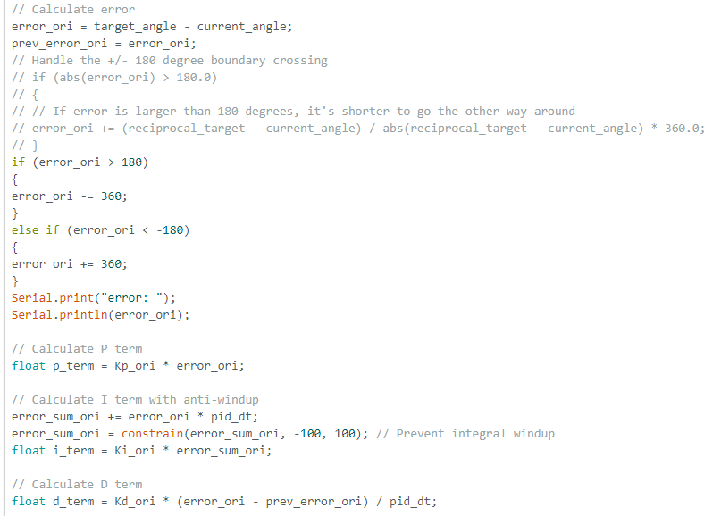
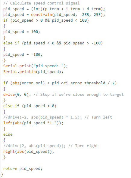
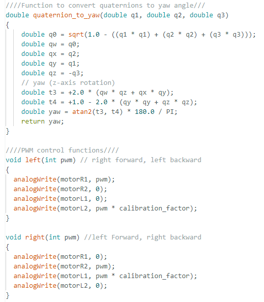
For this function, I had mostly the same code from lab 6 however I made some new changes and added the dmp handling where I had a function to handler quaternion to yaw. I also had to edit my error boundaries to handle the +/- 180 degree coundary crossing. If the error_ori was more than 180 I would minus 360 from the error to ensure that the error would not wrongly increase causing the pwm to spin wildly out of control. If the error was less than -180 I did the same thing and printed out the error to debug. I also had code to calculate the PID terms similar to how I did in previous labs. Most of my woes for this lab was actually tuning the car to work on the lab floor. There were many times when my PID control would work on a table where there was less friction thus less PWM to get the car to spin but on the lab floor the car had a much harder time to move. To deal with this issue I had another part to handle the speed control where the PID terms would not be enough to fix. I had a bounding condition where if the PID speed was between 0 to +/- 100, I would manually set the pid_speed to 100. Through much trial and error I had decided that 100 was the minimum speed needed for the car to turn nicely on the lab floor. This speed however would sometimes change based on the battery charge so I had to change this value all the time. I also had a calibration factor of 1.3 to ensure that the left and right turning would keep the car on its axis. My PID values were 1.3, 0.1, 0.5 respectively.
After coding out the PID, here is a video of the two turns I did on the floor. In the first video the car is really turning on a perfect axis. In the second video, the car is not able to stay on an axis but corrects itself. It looks like the car doesn't make a full 360 degrees because I had the code have the car stop on the increment right before reaching 360.
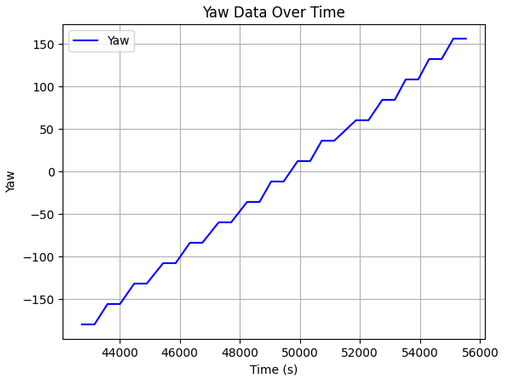
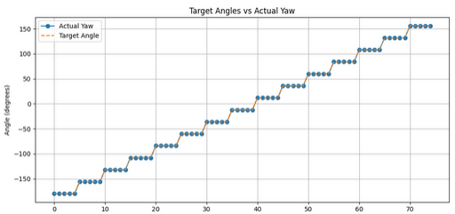
I plotted the values of yaw for each 24 degree turn over time. I compared it with the target angles of the PID controller and as seen the PID controller works pretty well. I was unable to do a full 360 degree turn but was able to get from around -180 to around 150 degrees totalling up to around 340 degrees of mapping. I plotted out the target angle and compared it with the actual yaw and saw that the PID controller worked pretty accurately to a surpising degree. The slight variation in the yaw value was also very small. Below is a graph that compared the target angle with the actual yaw as well as yaw over time. There were more yaw values than target angles so I had to repeat the target angles to get the necessary data points.
I also analyzed the average increments to see if the yaw increment was actually always 24 degrees which it was. With this data I could see that the average error would be very small. The final angle of a 360 degree turn would be 156 from -180 which would amount to a total 336 degree turn for mapping giving me a large difference of 24. I think I could have coded my car to do one extra turn to get to a full 360 but I believe due to my conditions and control flow and to ensure my car wouldn't go crazy sometimes I had it stop right before it reached 360. With a floor with less friction, the robot moved much more accurately and smoothly while I noticed a floor with much more friction caused the robot to move more out of axis around 30 mm max. 30 mm/14 readings would give a max error in actual position to be 2.14 mm. The average acceptable error between starting and ending position wwas around 22 mm leaving a 1.57 mm average error in position.
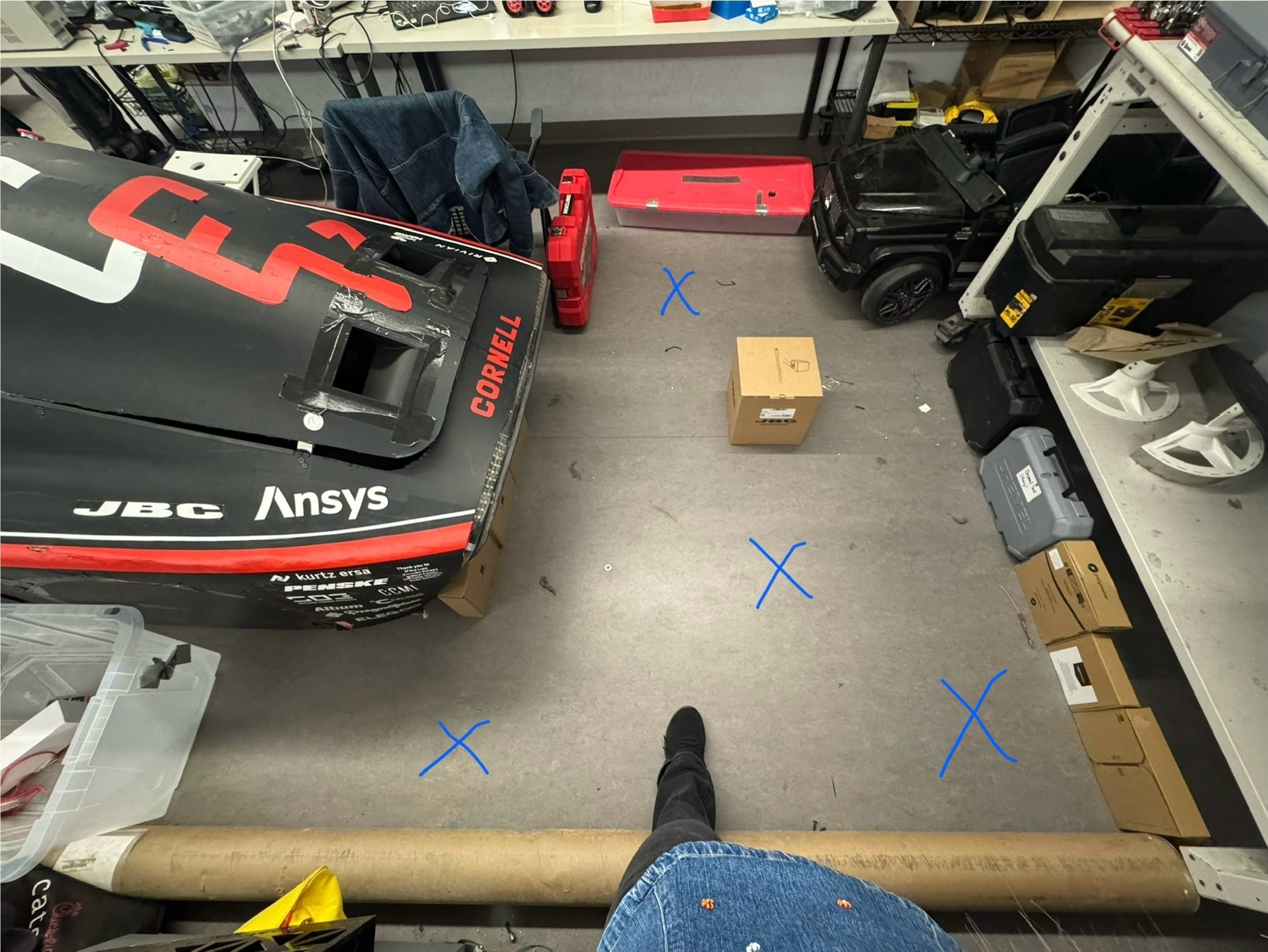
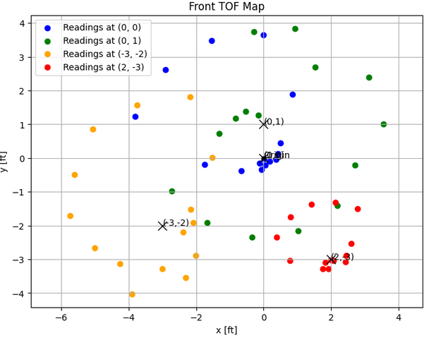
I would collect data for each mapping on different areas of the ELL "map" in a csv. Due to time constraints I was not able to test on the actual lab map. Below is a photo of the "map" I was using in the ELL using points (0,0) which is the cross in the middle, (-3, -2), (2, -3), and (0, 1). The distance was meausred using the front TOF sensor and the data was sent via bluetooth after each mapping. The robot started at the same orientation facing front wards. I had a total variable that added the angle the robot stopped at the previously recorded stopping angle to account for when the robot did not stop at exactly 24 degrees. I think in some of the runs I was in the middle of the map and was a moving obstacle that might have put noise into the data sometimes.
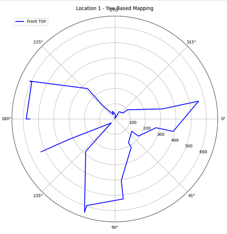
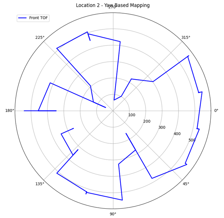
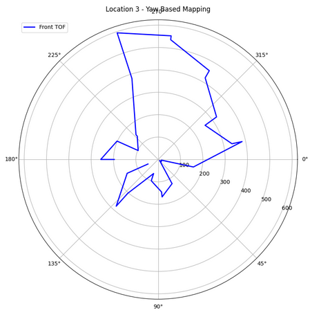
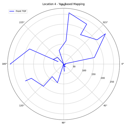
With each reading I collected data and put it in a polar coordinate frame plot to ensure the readings made sense. Unfortunately I had some noise which made it difficult to determine the exact walls. I had to position the TOF sensor to point more upwards to get the data. Belwo are my coordinate plots as well as plots of my TOF distance data over time. I think I could have gotten better data if I make the increments smaller. I think the larger increments caused the plots to miss some aspects of my map such as the tiny box in the middle that would have caused the distance to be very small for the sensor to sense at certain angles. I did make sure all the robots orientations started the same way but I think the noise and the wide turns on the axis made the data a bit hard to cypher.
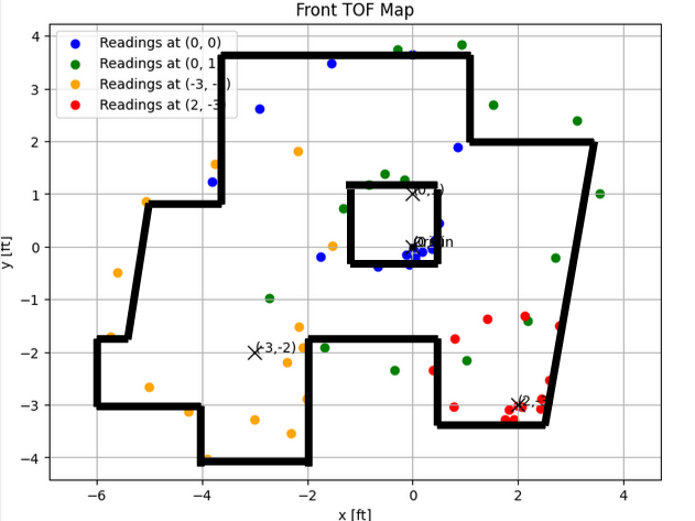
After getting the data from different parts of the map, I plotted the distances in a global frame using the below transformation matrix. I also plotted it all in the polar plot to see how it would all come together. I color coded the data points and set the matrices up for the coordinate points on the map. I did guestimate the coordinate points when doing it first because this was my own map so later I did have to go through trial and error on the coordinates to get a global frame that best represented the map the robot was in. I just used the TOF sensor on the front of the car and used the best data set that best represented the map to merge. Below is my code for one location and the necessary graphs of the merge data.


After plotting the above graph, I plotted lines that represented the walls of the map. This graph can be shown below. Some errors were found in this. I think it might have been because my walls were not that well defined unlike in the lab space and I was walking around a lot or trying my best to hide from the sensor when I was collecting data. The little divet at the bottom was where I stood to take some of the data.
I referenced Stephan Wagner and Mikayla Lahr for implementation. I used Sana Chawla's car for data collection because my car's motor controllers did not work as well. I referenced Lulu's code for some of the boundary conditions/ speed issues I had.